
DOWNLAOD FULL BOOK. PDF1 Features Implementation This was just too good of a project to not do, so I jumped straight into it and built it. The Light Source I was originally planning to use some of the UV tubes available from the local Jaycar. They have UV and blacklight flourescents, UV LEDs, UV CCFLs, but not detailed specifications on the UV wavelength emitted - but most importantly me, they couldn't tell me whether they were suitable for UV exposure. After a bit of web searching, I found mention of someone having success with the NEC UV lights. A bit more searching and I found them available from Kalex. Not only do they sell the tubes, but they sell UV Light Boxes, which I assume use these tubes. And they also sell Kinsten, and developer, so this seemed to be the right source. They sell 3 tube sizes... I selected the 15 Watt size because it used a standard G13 fitting, available from my local hardware store. I had also picked up a dozen 15 Watt UV ballasts for $1.50 each from Rockby which matched perfectly. I know now that I could have got the G8 fittings from Middendorp. I could have also got electronic Ballasts that could drive 4 tubes, making the whole case smaller, but costing a lot more. Box Construction As I normally do, I obtained at least one of each components, measured them up and entered then into ProDesktop Express. Then I put together the design, a simple plywood box, with a lip around the edge to sit the glass. The only design parameter, apart from fitting everything in, was to ensure that the lights remained 5cm away from the circuit board being exposed. Nothing really tricky here. Well it shouldn't have been, except that I nailed together the front face of the box upside down, so that the timer circuit was a bit too high, and ran into the ledge. It still worked though. Timing Circuit The timing circuit gave me the opportunity to use one of the 8 character 5x5 LED display units I got on special from Rockby. I got them for about $3 each - they are back to their regular prices of $32 - OUCH! To drive the display I grabbed a AT90S2313 that I had lying around, a couple of 240V rated relays to switch the top and bottom banks of lights independently, and a buzzer to buzz. Unfortunately I forgot to add the case open sensing switch to be able to turn off the lights if the box was opened. Another enhancement I would have added was a light detector or two to sense when they lights are on - the fluorescent lights can take a couple of seconds to light, so I would have liked to take that into account before starting the count down timer. The circuit was pretty simple, as it usually is with a microcontroller. The circuit board was my first attempt at a double sided board. Not only were there tracks on both sides of the board, there components placed on both sides. This was done because the relays where big and chunky. It was also easier to have the power connector coming in from behind. The buzzer was a bit too tall and should have been on the back.Power Diameter (mm) Length (mm) Fitting 8 Watt 15.5 287 G8 15 Watt 25.5 436 G13 20 Watt 32.5 588.5 G13 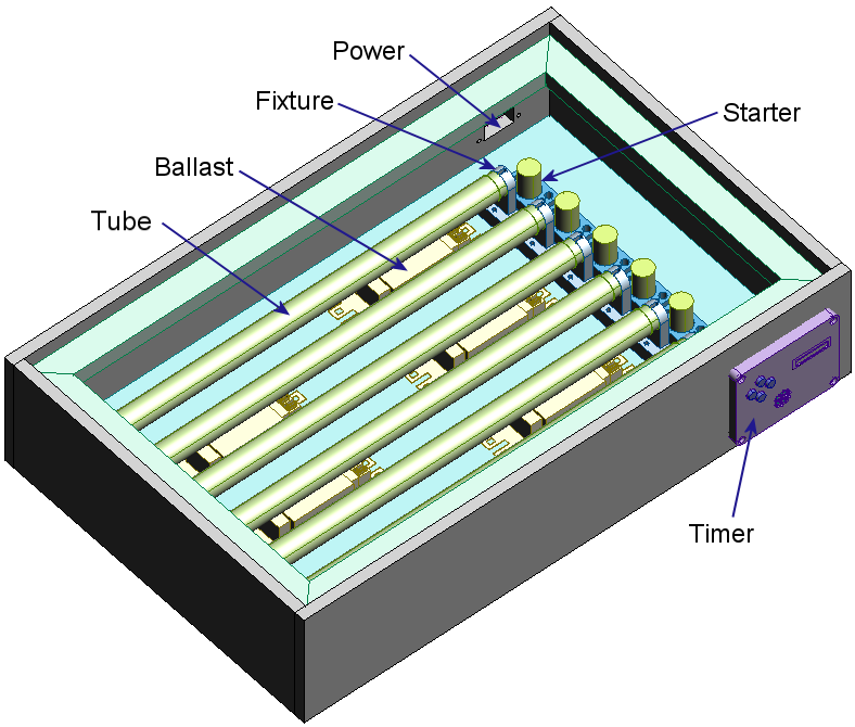
UV EXPOSURE LIGHT BOX
Labels: VU Exposure Tool Box


Subscribe to:
Post Comments (Atom)

1 comments:
Hi there would you mind letting me know which
webhost you're working with? I've loaded your blog in 3 completely different web browsers and I must say this blog
loads a lot quicker then most. Can you suggest a good web hosting provider at a honest price?
Many thanks, I appreciate it!
Also visit my web-site :: vrbo tucson estates
Post a Comment