DOWNLOAD FULL BOOK : PDF1 CHAPTER 1 TELECOMMUNICATIONS BUILDING CABLING SYSTEM CHAPTER 2 BUILDING TELECOMMUNICATIONS CABLING SYSTEM SPECIFICATIONS FIGURES Download : pdf1
1-1 OVERVIEW
1-2 References
1-3 ACRONYMS AND ABBREVIATIONS
1-4 Responsibilities
1-5 Scope
1-6 Objective
2-1 Classified Information Infrastructure
2-2 System Overview
2-3 Workstation Outlet
2-4 Building Telecommunications Wiring
2-4.1 Horizontal Cable
2-4.1.1 Copper Voice and Data
2-4.1.2 Fiber Optic Cable
2-4.1.3 Cable Length
2-4.2 Backbone Cable
2-4.2.1 Copper Backbone Cable
2-4.2.2 Copper Termination
2-4.2.3 Fiber Optic Backbone Cable
2-4.3 CATV or CCTV Cable 2-4.4 Building Infrastructure
2-5 Telecommunications Room
2-5.1 Multi-Story Buildings
2-5.2 Telecommunications Room Sizing
2-5.3 Room Interior Finishes
2-5.4 Room Door
2-5.5 Room Location
2-5.6 Telephone Backboards
2-5.7 Equipment Racks
2-5.8 Equipment Cabinets
2-5.9 Unshielded Twisted Pair Patch Panels
2-5.10 Fiber Optic Patch Panels
2-5.11 Ladder and Wire Cable Tray
2-5.12 Room Lighting
2-5.13 Room Climate Control
2-5.14 Room Contaminants
2-5.15 Electrical Power
2-5.16 Voice Communications
2-6 Equipment Room
2-6.1 Equipment Room Provisioning
2-7 Grounding
2-7.1 Building Earth Electrode Subsystem (EES)
2-7.2 Cable Entrance Grounding
2-7.3 Telecommunications Room Signal Ground
2-7.4 Telecommunications Rack and Supporting Structure
2-8 Telecommunications System Labeling
2-8.1 Outlet/Patch Panel Labels
2-8.2 Conformance to Existing Standards
2-8.3 Telecommunications Outlet Labeling
2-8.4 Telecommunications Patch Panel Labeling
2-8.5 Distribution System Labeling
2-9 Building Entrance Facility
2-9.2 Protected Entrance Terminals (PET)
2-9.3 Fiber Termination Device
2-10 Testing
2-10.1 Unshielded Twisted Pair Tests
2-10.2 Category 5e and 6 Circuits
2-10.3 Coaxial Cable
2-10.4 Fiber Optic Cable
Figure 1 TELECOMMUNICATIONS ROOM ENTRANCE AND BACKBONE DIAGRAM2
Figure 2 TELECOMMUNICATIONS ROOM HORIZONTAL DISTRIBUTION DIAGRAM
Figure 3 TELECOMMUNICATIONS ROOM STANDARD SUPPORTING STRUCTURE AND BACKBONE
Figure 4 TELECOMMUNICATIONS ROOM STANDARD PREMISE DISTRIBUTION
Figure 5 TELECOMMUNICATIONS ROOM HIGH DENSITY PREMISE DISTRIBUTION
Figure 6 TELECOMMUNICATIONS OUTLET TYPES
Figure 7 SYSTEMS FURNITURE WIRING
Figure 8 PREMISE DISTRIBUTION SUPPORTING STRUCTURE - RENOVATION
Figure 9 TYPICAL FLOOR PLAN
Figure 10 J-STD-607A GROUNDING
Figure 11 MIL-STD-188-124B GROUND
Telecommunications Building Cabling Systems Planning and Design
2 commentsLabels: Building Cabling system
Working Safely with Photovoltaic System
0 commentsLabels: working Safely with Photovoltic
TOC 1. Introduction 2. About This Booklet 3. PV System Characteristics and Hazards 3.1 PV System Characteristics 3.2 System Hazards and Recommendations 4. Safe PV Systems 5.0 For Your Health download : pdf1
3.1.1 Types of Systems
3.1.2 Balance of Systems
3.2.1 Non-Electrical Hazards
3.2.2 Electrical Hazards
3.2.3 Battery Hazards
3.2.4 AC Power Hazards
4.1 Applicable Safety Codes
4.2 Designing and Installing a PV System-
What the NEC Says
4.2.1 System Current and Voltage
4.2.2 Wiring and Disconnect Requirements
4.2.3 Grounding
4.2.4 The PV System Output
4.3 Testing a PV System–Safety Hints
5.1 Non-Electrical Injuries
5.2 Electrical Injuries
Security Engineering : Electronic Security System
0 commentsLabels: Security engineering
DOWNLAOD FULL BOOK :: PDF
CHAPT 1 INTRODUCTION
1-1 PURPOSE
1-2 SCOPE1-3 REFERENCES
1-4 GLOSSARY
1-5 SECURITY ENGINEERING UFC SERIES
1-6 ORGANIZATION OF THIS UFC
CHAPT 2 ELECTRONIC SECURITY SYSTEM OVERVIEW 2-1 OVERVIEW
2-2 DETECT, DELAY, AND RESPOND
2-3 ESTABLISH REQUIREMENTS2-4 SYSTEM COMPLEXITY
2-5 MONITORING METHODS
CHAPT 3 ACCESS CONTROL SYSTEMS
3-1 OVERVIEW3-2 ACS ENTRY-AUTHORIZATION IDENTIFIERS3-3 OTHER ACS IMPLEMENTATION CONSIDERATIONS
3-4 ACS EQUIPMENT
3-5 ACS DESIGN GUIDANCE
CHAPT 4 CLOSED CIRCUIT TELEVISION SYSTEMS
4-1 OVERVIEW
4-2 DIGITAL VIDEO RECORDER (DVR)
4-3 SYSTEM DISPLAYS
4-4 VIDEO MATRIX SWITCHERS4-5 KEYBOARDS
4-6 CAMERAS
4-7 INTERNET PROTOCOL (IP) ADDRESSABLE CAMERAS4-8
RECORDING
4-9 ILLUMINATION
4-10 VIEWING IN LOW-LIGHT CONDITIONS
4-11 POWER
4-12 CAMERA FIELDS-OF-VIEW4-13 RESOLUTION
4-14 FRAMES PER SECOND (FPS)
4-15 BANDWIDTH
4-16 WHITE BALANCE
4-17 CCTV CAMERA EMPLOYMENT FOR INTRUSION DETECTION
4-18 CCTV EQUIPMENT CONSIDERATIONS4-19 CCTV SYSTEMS DESIGN GUIDANCE
CHAPT 5 INTRUSION DETECTION SYSTEM5-1 OVERVIEW
5-2 CENTRAL PROCESSING UNIT (CPU)
5-3 INTERIOR SENSORS
5-4 EXTERIOR SENSORS
5-5 SYSTEM CONFIGURATION
5-6 IDS DESIGN GUIDANCE
5-7 SUMMARY
CHAPT 6 DATA TRANSMISSION MEDIA (DTM)6-1 INTRODUCTION
6-2 BANDWIDTH ANALYSIS
6-3 SECURE COMMUNICATIONS
6-4 NETWORK TOPOGRAPHY6-5 COMMUNICATION REDUNDANCY
6-6 TRANSMISSION MODES/PROTOCOLS
6-7 TRANSMISSION MEDIA
6-8 TECHNOLOGY COMPARISION
6-9 ENCRYPTION
CHAPT 7 DISPATCH CENTER 7-1 INTRODUCTION7-2 SPACE
7-3 LIGHTING
7-4 CONSOLES
7-5 MONITORS
7-6 GROUNDING/POWER CONDITIONING
7-7 HVAC7-8 SUPPORT ROOMS
CHAPT 8 ESS SUBSYSTEM INTEGRATION
8-1 OVERVIEW
8-2 COMMUNICATION FROM THE IDS TO THE ACS
8-3 COMMUNICATION FROM THE IDS TO THE CCTV SYSTEM
8-4 COMMUNICATION FROM THE CCTV SYSTEM TO THE ACS
8-5 COMMUNICATION FROM THE ACS TO THE DISPATCH CENTER
8-6 COMMUNICATION FROM THE DISPATCH CENTER TO THE ACS
8-7 BANDWIDTH ANALYSIS

CHAPT 9 GENERAL REQUIREMENTS AND CROSS-DISCIPLINE COORDINATION
9-1 GENERAL REQUIREMENTS
9-2 GENERAL COORDINATION
9-3 CIVIL COORDINATION
9-4 ARCHITECTURAL COORDINATION
9-5 LIFE SAFETY CODE CONSIDERATIONS
9-6 ELECTRICAL COORDINATION
9-7 MATERIAL ENTRY CONTROL
CHAPT 10 MODEL DESIGN APPROACH
10-1 INTRODUCTION
10-2 PROJECT PLANNING
10-3 INITIAL DRAWING PREPARATION
10-4 BASIS OF DESIGN
10-5 SCHEMATIC DESIGN PHASE
10-6 DESIGN DEVELOPMENT PHASE
10-7 BIDDING
Steam Power Plants:
1 commentsLabels: Steam Power PLants
DOWNLOAD FULL BOOK : PDF Section 1 INTRODUCTION Section 2 BASIC DATA Government Ownership Section 3 ADMINISTRATIVE PROCEDURE TO DEVELOP A POWER PLANT Section 4 POWER PLANT STEAM GENERATION Section 5 STEAM TURBINE DESIGN Section 6 GENERATOR AND ELECTRICAL FACILITIES DESIGN6.1 Typical Voltage Ratings and Systems Section 7 STEAM CONDENSERS Section 8 AUXILIARY EQUIPMENT Section 9 COAL HANDLING Section 10 ASH HANDLING ..................... MORE
1.1 Scope
1.2 Cancellation
1.3 Policy 2.1 Economic Analysis
2.2 Economic Studies
2.3 Source of Power
2.4 Private Versus
2.5 Expansion, Rehabilitation, and Replacement of Existing Plants
2.6 Fuel Selection
2.7 Codes and Regulations
2.8 Plant Location Factors
2.9 Types of Power Plants
3.1 Power Plant Loads
3.2 Steam Power Plant Design
3.3 Plant Design Factors
4.1 Steam Generators (Boilers)4.2 Steam Pressures and Temperatures
4.3 Natural Gas Firing
4.4 Fuel Oil Firing
4.5 Coal Firing
4.6 Wood Firing4.7 Soot Blowers
4.8 Economizers
4.9 Air Heaters
4.10 Forced Draft Fans
4.11 Induced Draft Fans
4.12 Primary Air Fans
4.13 Overfire Air Fans
4.14 Cinder Return Fans
4.15 Stacks
4.16 Blowdown Equipment
4.17 Essential Plant Equipment
4.18 Equipment Selection
5.1 Typical Plants and Cycles
5.2 Cogeneration in Steam Power Plants
5.3 Turbine Types
5.4 Turbine Generator Sizes
5.5 Turbine Throttle Pressure and Temperature
5.6 Turbine Exhaust Pressure
5.7 Lubricating Oil Systems
5.8 Generator Types
5.9 Generator Cooling
5.10 Turbine Generator Control
5.11 Turning Gear
5.12 Turbine Generator Foundations
5.13 Auxiliary Equipment
5.14 Installation
5.15 Cleanup, Startup, and Testing 5.16 Operation
6.2 Generators6.3 Generator Leads and Switchyard
7.1 Condenser Types
7.2 Condenser Sizes
7.3 Condenser Materials
7.4 Condenser Support
7.5 Condenser Air Removal
8.1 Condensate Storage and Transfer
8.2 Feedwater Heaters
8.3 Heater Drain Pumps
8.4 Deaerators
8.5 Boiler Feed Pumps
8.6 Pressure Reducing and Desuperheating Stations
8.7 Compressed Air System
8.8 Auxiliary Cooling Water System
9.1 Unloading Systems
9.2 Coal Crushing
9.3 Coal Storage
9.4 Coal Reclaiming
9.5 Plant Bunker or Silo Storage
9.6 Bunker or Silo Filling Systems
9.7 Coal Scales
9.8 Magnetic Separators
9.9 Coal Sampling
10.1 Ash Handling Systems
10.2 Bottom Ash Hoppers
10.3 Clinker Crushers
10.4 Ash Storage
Diesel Electric Generating Plants
0 commentsLabels: diesel electrical Generator
DOWNLOAD FULL BOOK : PDF
Section 1 INTRODUCTION
1.1 Scope
1.2 Diesel-Electric Generating Plant Types
1.3 Definitive Designs and Guide Specification
1.4 Usage

Section 2 POLICY
2.1 Diesel-Electric Generating Plant Design
2.2 Sources of Electric Power
2.3 Duty Types and Loads
2.4 Planning Considerations
2.5 Commercial Versus Government Ownership (Prime Duty Only)2.6 Fuel Selections
2.7 Reliability and Maintainability2.8 Economic Studies
Section 3 INFORMATION REQUIRED FOR DESIGN
3.1 Introduction
3.2 Electrical Loads
3.3 Duty and Capacity Requirements for Electric Generating Plants
3.4 Plant Location Factors
3.5 Cogeneration Information
3.6 Checklist for Facility Interfaces
Section 4 COGENERATION CONSIDERATIONS
4.1 Introduction4.2 Design Considerations
4.3 Heat Recovery Applications
Section 5 DEFINITIVE DESIGNS FOR DIESEL-ELECTRIC GENERATING PLANTS5.1 Definitive Diesel-Electric Generating Plants
5.2 Criteria for Unit and Plant Capacities
5.3 Selection of Unit Capacity
5.3.1 Ability to Serve Load Under Abnormal Conditions
5.3.2 Load Shedding
5.3.3 Spinning Reserve
5.3.4 Type of Load Served
5.4 Fuel Selection
Section 6 SYNCHRONOUS GENERATORS, EXCITATION, AND REGULATION
6.1 General
6.2 Synchronous Generators
6.3 Excitation and Voltage Regulation
6.4 Paralleling and Synchronizing
Section 7 ENGINE CONTROLS AND INSTRUMENTS
7.1 General
7.2 Speed Governing System
7.3 Controls
7.4 Instrumentation
Section 8 GENERATOR CONTROLS AND PROTECTION
8.1 Control Capabilities
8.2 Control Locations
8.3 Operating Control Requirements
8.4 Generator Protection
Section 9 BUILDING CONSTRUCTION FOR DIESEL-ELECTRIC GENERATING PLANTS
9.1 Building Construction
9.2 Single-Level Diesel-Electric Generating Plant Layout 9.3 Two-Level Diesel-Electric Generating Plant Layout
Section 10 NONSTANDARD DIESEL-ELECTRIC GENERATING PLANTS10.1 Conditions for Nonstandard Plant Selection
10.2 Gasoline Engine Electric Generators
10.3 Gaseous and Dual Fuel Engines
10.3.1 Gas Heating Value
10.3.2 Wet Gas Treatment
10.3.3 Gas Supply Shut-Off
10.3.4 Gas Pressure
Section 11 WATER CONDITIONING
Section 12 PIPING
Section 13 INSULATION
Section 14 CORROSION PROTECTION
Section 15 MISCELLANEOUS CRITERIA
Interior Electrical Systems
0 commentsLabels: Electrical Interiors
DOWNLOAD FULL BOOK : PDf 1. General 1-1 PURPOSE PRELIMINARY AND DETAILED DESIGN ANALYSIS GENERAL POWER SYSTEM CRITERIA POWER DISTRIBUTION AND UTILIZATION—TRANSFORMERS CHAPTER 5 POWER DISTRIBUTION AND UTILIZATION—SWITCHGEAR, LOAD CENTERS, AND BREAKERS 5-1 SERVICE ENTRANCE CHAPTER 6 POWER DISTRIBUTION AND UTILIZATION—RACEWAY AND WIRING 6-1 RACEWAY CRITERIA CHAPTER 7 POWER DISTRIBUTION AND UTILIZATION—MOTORS AND MOTOR CONTROL CIRCUITS 7-1 BASIC MOTOR CRITERIA CHAPTER 8 POWER DISTRIBUTION AND UTILIZATION—OTHER DESIGN CRITERIA 8-1 ELECTRICAL EQUIPMENT CLEARANCES AND GUARDS CHAPTER 9 ELECTRICAL SYSTEM PROTECTION AND COORDINATION 9-1 PROTECTION SYSTEM DESIGN FOR MORE>>>>>>>>>>>>>> download : PDF
1-2 SCOPE
1-3 REFERENCES
1-4 CODES AND STANDARDS
1-5 SYMBOLS
1-6 APPLICABILITY 1-7 MANUAL CONTENT AND ORGANIZATION
2-1 PRELIMINARY DESIGN
2-1.1 Principal Points of Contact2-1.2 Preliminary Design Guidance for Interior Electrical Systems
2-1.3 Unified Facilities Guide Specifications
2-2 ELECTRICAL LOAD CRITERIA
2-3 OVERVIEW OF DETAILED ANALYSIS CRITERIA
2-4 SHORT CIRCUIT ANALYSIS2-4.1 Analysis and Equipment Criteria
2-4.2 Short Circuit Sources
2-4.3 Symmetrical Versus Asymmetrical Current
2-4.4 Short Circuit Calculations
2-5 POWER FLOW ANALYSIS
2-6 VOLTAGE DROP ANALYSIS
2-6.1 Voltage Drop Calculations
2-6.2 Motor Starting Studies2-7 ELECTRICAL COORDINATION
2-8 POWER QUALITY AND HARMONIC DISTORTION
2-9 LIGHTING
2-10 ENERGY ANALYSIS
2-10.1 Overview
2-10.2 New Facility Criteria
2-10.3 Existing Facilities
2-10.4 Energy Efficiency Design Opportunities in the Electrical System
2-11 LIFE-CYCLE COST ANALYSIS
2-12 ELECTRICAL DRAWINGS
2-12.1 Introduction
2-12.2 One-Line Diagrams
2-12.3 Switchgear Lineups
2-12.4 MCC Layouts
2-12.5 Grounding
2-12.6 Control Panel Wiring Diagrams
2-12.7 Control Schematics
2-12.8 Miscellaneous Interconnection Diagrams
2-12.9 Equipment Layouts with Conduit or Cable Tray
2-12.10 Panel Schedules
2-12.11 Lighting and Receptacle Layouts
2-12.12 Motor List
2-12.13 Conduit or Cable Schedule
3-1 CHARACTERISTICS 3-1.1 Voltage
3-1.2 Frequency
3-1.3 Power Factor
3-1.4 Neutral Conductor Grounding
3-2 NORMAL POWER SOURCE
3-3 ALTERNATE AND BACKUP POWER SOURCE
3-4 SERVICES
4-1 RATINGS
4-1.1 Introduction
4-1.2 Voltage and Current
4-1.3 Temperature and kVA
4-1.4 Impedance
4-1.5 Number of Phases
4-1.6 Transformer Taps
4-1.7 Noise
4-1.8 Basic Impulse Insulation Levels (BILs)
4-2 LOW VOLTAGE TRANSFORMERS
4-3 MEDIUM VOLTAGE TRANSFORMERS
4-4 OTHER TRANSFORMERS
4-4.1 Isolation Transformers
4-4.2 Buck-Boost Transformers
4-4.3 K-Factor Transformers
4-4.4 Specialty Transformers
4-5 TRANSFORMER INSTALLATION CRITERIA
4-5.1 Introduction
4-5.2 Dry-Type Transformers
4-5.3 Less-Flammable, Liquid-Insulated, and Oil-Insulated Transformers
4-5.4 Fire Protection Criteria
4-6 TRANSFORMER SIZING
4-7 INFORMATION SOURCES
5-2 SWITCHGEAR AND SWITCHBOARDS GENERAL CRITERIA
5-3 HIGH VOLTAGE SWITCHGEAR
5-4 MEDIUM VOLTAGE SWITCHGEAR
5-4.1 Ratings
5-4.2 Low Voltage Conductors in Medium Voltage Switchgear
5-5 LOW VOLTAGE BREAKERS AND PANELS
5-6 MOTOR CONTROL CENTERS
5-7 DISCONNECT SWITCHES
5-8 CIRCUIT LOCKOUT REQUIREMENTS
5-9 INFORMATION SOURCES
6-2 WIRING SYSTEM CRITERIA
6-3 SIZING WIRING SYSTEMS FOR ENERGY SAVINGS
6-4 CONVENIENCE OUTLETS AND RECEPTACLES
6-5 WIRING FOR TEMPORARY POWER AND LIGHTING
6-6 ACCEPTANCE TESTING OF WIRING SYSTEMS
7-2 MOTOR CONTROL CIRCUITS
7-3 ADJUSTABLE SPEED DRIVES
8-1.1 Background
8-1.2 Equipment Rated 600 Volts and Lower
8-1.3 Equipment Rated Above 600 Volts
8-2 ENCLOSURES
8-3 HAZARDOUS LOCATIONS
8-4 400-HERTZ DISTRIBUTION SYSTEMS
8-5 METERING
8-6 POWER FACTOR CORRECTION
9-2 ELECTRICAL COORDINATION ANALYSIS CRITERIA
9-2.1 Introduction
9-2.2 Coordination Study Description
9-2.3 Coordination Time Intervals
9-2.4 Pickup Current
9-2.5 Coordination Curves
9-2.6 Coordination Analysis
9-2.7 Coordination Study Report
9-3 PROTECTIVE RELAYS
9-4 INSTRUMENT TRANSFORMERS
9-4.1 Background
9-4.2 Current Transformers
9-4.3 Potential Transformers
9-5 FUSES
9-6 OVERLOAD RELAYS
9-7 CIRCUIT BREAKERS
9-8 PROTECTIVE DEVICE DESIGNATIONS
9-9 INFORMATION SOURCES
Cathodic Protection
1 commentsLabels: Cathodic Protection
DOWNLOAD FULL BOOK : PDF
TOC 1. INTRODUCTION TO CATHODIC PROTECTION Purpose References Corrosion Cathodic protection Types of cathodic protection systems 2. CATHODIC PR OTECTION DESIGN Required information Determining the type and design of cathodic protection system APPENDIX A SOIL RESISTIVITY MEASUREMENT B CURRENT REQUIREMENT TESTING C EXAMPLES OF GALVANIC CATHODIC PROTECTION DESIGN D EXAMPLES OF IMPRESSED CURRENT CATHODIC PROTECTION DESIGN E SPECIFICATIONS FOR CERAMIC ANODE F RECTIFIER CURRENT INTERFERENCE LIST OF FIGURES 1-1 Corrosion of a pipeline due to localized anode and cathode sites 1-2. Galvanic and impressed current systems for cathodic protection 2-1. Design sequence for cathodic protection systems A-1. Wenner four-pin method for measuring resistivity A-2. Soil box for soil resistivity measurements B-1. Current requirement test on pipelines C-1. Galvanic anode cathodic protection for hydrant refueling system C-2. Galvanic anode cathodic protection for underground steel storage tank C-5. Layout of gas piping in residential district D-l. Cathodic protection system for gas main D-2. Impressed current cathodic protection for heating conduit system D-3. Cathodic protection for black iron hot water storage tank D-4. Fringe factor for stub anodes D-5. Dimensions for an elevated steel water tank D-6. Cathodic protection for tanks using rigid-mounted button-type anodes and platinized titanium wire D-7. Segmented elevated tank for area calculations D-8. Anode spacing for elevated steel water tank D-9. Anode suspension arrangement for elevated steel water tank D-10. Equivalent diameter factor for anodes in a circule in water tank
Electrical Power Supply and Distribution
0 commentsLabels: Electrical Power supply
Download : Pdf1.
1. GENERAL
Purpose
Scope
References
Standards and CodesPower Supply Design Criteria
Electrical Power Sytems
Design Procedures
Evaluation and Selection of Energy Systems Design Analysis
Service Conditions
Explanation of Abbreviations and Terms
2. ELECTRICAL POWER REQUIREMENTS
General
Load Estimation
3. VOLTAGE SELECTIONGeneral
System Voltage Classifications
Selection of Primary Distribution Voltage for New Installations
Selection of Primary Distribution Voltage for Existing Installation
s
Commercial Power for Air Force Installations
Selection of Primary Distribution Voltage for Air Force Installations
4. MAIN ELECTRIC SUPPLY STATIONS/SUBSTATIONS
ProvisionsOwnershipStation Designation and Elements
Main Electric Supply Station/Substation
Environmental Aspects
Incoming Line Switching Equipment
Substation Equipment
Miscellaneous Station Design Criteria
Substation Equipment at Air Force Installations
5. ELECTRIC DISTRIBUTION LINES
Selection
Types of Underground LinesTypes of Aerial Lines
Voltage Drop
Power Factor Correction
Medium-Voltage Circuits
Pad-Mounted Line Sectionalizing EquipmentJoint Electrical/Communication Lines for Air Force Installation
6. AERIAL DISTRIBUTION LINES
General
Installation Considerations
Conductors
Poles
Circuit Configurations
Insulators
Guying
Miscellaneous ItemsAir Force Installations
7. UNDERGROUND DISTRIBUTION LINES
General Cable
Cable
Duct Lines
Manholes, Handholes, and Pullboxes
Direct-Burial Cable Installations
8. TRANSFORMER INSTALLATIONS
Definitions
Installation of Distribution-to-Utilization Voltage Transformers
Installation of Transmission-to-Distribution Voltage Transformers
Transformer Dielectrics
Transformer Characteristics
Amorphous Metal-Core TransformersTransformers at Air Force Installations

9. SURGE PROTECTION AND GROUNDING
Voltage Surges and Potential Gradients
Methods of Controlling Voltage Surges and Potential Gradients
Ground Electrodes
Grounding Details and Requirements
10. ROADWAY AND AREA LIGHTING
General
Roadway Lighting Design
Area Lighting Design
Walkway and Bikeway Lighting Design
Light Sources
Lighting Control and Wiring System
11. SECURITY LIGHTING
General
Authorization
Use of Security Lighting Systems
Types of Areas to be Lighted
Lighting Guidelines
Light Sources
Electrical Power Sources
Luminaries
Wiring and Control
Field Measurement
Modern Signal Processing
0 commentsLabels: Modern signal Processing
Introduction Hyperbolic Geometry,Nehari`s Theorem,Electric Circuits,and Analog Engineering Applications of the Motion-Group Fourier Transform FastX-Ray and Beam let Transforms for Three-Dimensional Data Fourier Analysis and Phylogenetic Trees Diffuse Tomography as a Source of Challenging Nonlinear Inverse An Invitation to Matrix-valued Spherical Functions Image Registration for MRI Image Compression: The Mathematics of JPEG2000 Integrated Sensing and Processing for Statistical Pattern Recognition Sampling of Functions and Sections for Compact Groups The Cooley-Tukey FFT and Group Theory Signal Processing in Optic Fibers The Generalized Spike Process, Sparsity and Statistical Independence download : zip1
Signal Processing![]()
Problems for a General Class o Networks
Control Valve Handbook
1 commentsLabels: Control Valve Handbook
DOWNLOAD FULL BOOK : Pdf.
1. Introduction to Control Valves1
What Is A Control Valve?
Process Control Terminology
Sliding-Stem Control Valve Terminology
Rotary-Shaft Control Valve Terminology
Control Valve Functions and Characteristics Terminology
Other Process Control Terminology
.imgcache)
2. Control Valve Performance
Process Variability
Economic Results
Summary
3. Valve and Actuator Types
Control Valves
Globe Valves
Rotary Valves
Control Valve End ConnectionsValve Body Bonnets
Control Valve Packing
Characterization of Cage-Guided Valve Bodies
Valve Plug Guiding
Restricted-Capacity Control Valve Trim
Actuators60
4. Control Valve Accessories65PositionersOther Control Valve Accessories
Limit Switches
Solenoid Valve Manifold
Supply Pressure Regulator
Pneumatic Lock-Up Systems
Fail-Safe Systems for Piston Actuators
Electro-Pneumatic Transducers
Electro-Pneumatic Valve Positioners
PC Diagnostic Software
5. Control Valve Selection
Valve Body Materials
Designations for the High Nickel Alloys
Pressure-Temperature Ratings for Standard Class
ASTM A216 Grade WCC Valves
Pressure-Temperature Ratings for ASTM A216 Cast Iron, ASTM B61 and B62 Cast Bronze Valves
Class Designation and PN Numbers
Face–to Face Dimensions
Wear & Galling Resistance Chart Of Material Combinations
Control Valve Seat Leakage Classifications
Class VI Maximum Seat Leakage Allowable
Typical Valve Trim Material Temperature Limits
Service Temperature Limitations for Elastomers
Ambient Temperature Corrosion InformationElastomer Information Fluid Compatibility
Control Valve Flow Characteristics
Selection of Flow Characteristic
Valve Sizing
Sizing Valves for Liquids
Abbreviations and Terminology
Equation Constants
Determining Fp, the Piping Geometry Factor
Determining qmax (the Maximum Flow Rate) or Pmax (the Allowable Sizing Pressure Drop)
Liquid Sizing Sample Problem
Sizing Valves for Compressible Fluids
Determining xTP, the Pressure Drop Ratio FactorRepresentative Sizing Coefficients for Single–Ported
Globe Style Valve Bodies
Representative Sizing Coefficients for Rotary Shaft Valves
Actuator Sizing
Rotary Actuator Sizing
Typical Rotary Shaft Valve Torque Factors
V–Notch Ball Valve with Composition Seal
High Performance Butterfly Valve with Composition SealNon-Destructive Test Procedures
Cavitation and Flashing
Choked Flow Causes Flashing and Cavitation
Valve Selection for Flashing Service, Valve Selection for Cavitation Service
Noise Prediction, Noise Control, Noise Summary
Packing Selection Guidelines
.........................More

Energy-Efficient Electric Motor Selection Handbook
0 commentsLabels: Energy Efficient electrical Motor
DOWNLOAD FLL BOOK : PDF 1. Introduction 2. Energy-Efficient Motor Performance and Price 3. How Much Can You Save ? 4. Obtaining Motor Efficiency Data5. Energy-Efficient Motor Selection Guidelines 6. Speed, Design Voltage, Enclosure, Part-load Efficiency, and Power Factor 7. Motor Operation Under Abnormal Conditions 9. Additional Benefits of Energy-Efficient Motors 10. Starting Your Motor Improvement Program 11. Energy-Efficient Motors : Twenty Questions and Answers DOWNLOAD : Pdf1
When to buy energy-efficient motors
Industrial motor population and uses
Annual electric motor sales
Motor Losses and Loss Reduction Techniques
Determining and Comparing Motor Efficiencies
Motor Efficienct Testing Standards
Testing Equipment Accuracy Limitations NEMA Motor Nameplate Labeling Standards
Understanding your Utility’s Rate Schedule
Determining Load Factor
Determining Operating Hours
Determining Annual Energy Savings
Motor Purchase Prices
Assessing Economic Feasibility
Recommendations for Motor Purchases
Initial Motor Purchases
Motor Failure and Rewind Scenario
Replacement of Operable Standard-Efficiency Motors
Oversized and Underload Motors
Sensitifity of Efficiency Gains to Motor RPM
Operating Voltage on Motor Performance
Motor Speed and Enclosure Considerations
Efficiency Improvements at Part-Load Conditions
Power Factor Improvement
Over Voltage
Under Voltage
Phase Voltage Imbalance
Load Shedding
8. Motor Selection Considerations
Motor Enclosures
Motor Insulation Systems
Service Factor
Motor Speed,Sip, and Torque Characteristics
Remote Sensing:
0 commentsLabels: Remote Sensing


Safety and Health Requirements
0 commentsLabels: Safety and Health Requirement
DOWNLOAD FULL BOOK... Pdf1. TABLE OF CONTENTS 1. Program Management 2. Sanitation 3. Medical and First-Aid Requirements 4. Temporary Facilities 5. Personal Protective and Safety Equipment 6. Hazardous Substances, Agents, and Environments 7. Lighting 8. Accident Prevention Signs, Tags, Labels, Signals, Piping System Identification, and Traffic Control FOR MORE DOWNLOAD.. PDF1.
A. General
B. Indoctrination and Training
C. Physical Qualification of Employees
D. Accident Reporting and Recordkeeping
E. Emergency Planning
F. Emergency Recovery Operations
A. General Requirements
B. Drinking Water
C. Toilets
D. Washing Facilities
E. Food Service
F. Waste Disposal
G. Vermin Control
A. GeneralB. First-Aid Kits
C. First-Aid Stations and Infirmaries
D. Personnel Requirements and Qualifications
A. General
A. General
B. Eye and Face Protection
C. Hearing Protection and Noise Control
D. Head Protection
E. Respiratory Protection
F. Body Belts, Harnesses, Lanyards, and Lifelines - Selection of Components
G. Electrical Protective Equipment
H. Personal Floatation Devices
I. Lifesaving and Safety Skiffs
A. General
B. Hazardous Substances
C. Hot Substances
D. Harmful Plants, Animals, and Insects
E. Ionizing Radiation
F. Nonionizing Radiation and Magnetic and Electric Fields
G. Ventilation and Exhaust Systems
H. Abrasive Blasting
I. Confined Space
J. Inclement Weather and Environmental Hazards
K. Cumulative Trauma Prevention
L. Indoor Air Quality (IAQ) Management
A. General
A. Signs, Tags, Labels, and Piping Systems
B. Signal Systems, Personnel, and Procedures
C. Traffic Control
D. Haul Roads..............
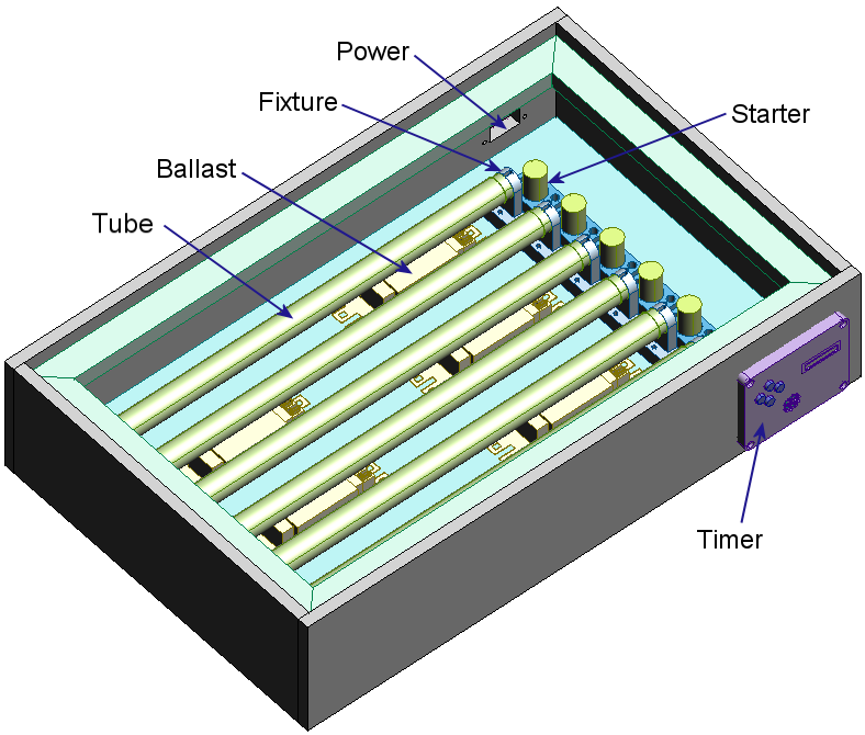
UV EXPOSURE LIGHT BOX
1 commentsLabels: VU Exposure Tool Box
DOWNLAOD FULL BOOK. PDF1 Features Implementation This was just too good of a project to not do, so I jumped straight into it and built it. The Light Source I was originally planning to use some of the UV tubes available from the local Jaycar. They have UV and blacklight flourescents, UV LEDs, UV CCFLs, but not detailed specifications on the UV wavelength emitted - but most importantly me, they couldn't tell me whether they were suitable for UV exposure. After a bit of web searching, I found mention of someone having success with the NEC UV lights. A bit more searching and I found them available from Kalex. Not only do they sell the tubes, but they sell UV Light Boxes, which I assume use these tubes. And they also sell Kinsten, and developer, so this seemed to be the right source. They sell 3 tube sizes... I selected the 15 Watt size because it used a standard G13 fitting, available from my local hardware store. I had also picked up a dozen 15 Watt UV ballasts for $1.50 each from Rockby which matched perfectly. I know now that I could have got the G8 fittings from Middendorp. I could have also got electronic Ballasts that could drive 4 tubes, making the whole case smaller, but costing a lot more. Box Construction As I normally do, I obtained at least one of each components, measured them up and entered then into ProDesktop Express. Then I put together the design, a simple plywood box, with a lip around the edge to sit the glass. The only design parameter, apart from fitting everything in, was to ensure that the lights remained 5cm away from the circuit board being exposed. Nothing really tricky here. Well it shouldn't have been, except that I nailed together the front face of the box upside down, so that the timer circuit was a bit too high, and ran into the ledge. It still worked though. Timing Circuit The timing circuit gave me the opportunity to use one of the 8 character 5x5 LED display units I got on special from Rockby. I got them for about $3 each - they are back to their regular prices of $32 - OUCH! To drive the display I grabbed a AT90S2313 that I had lying around, a couple of 240V rated relays to switch the top and bottom banks of lights independently, and a buzzer to buzz. Unfortunately I forgot to add the case open sensing switch to be able to turn off the lights if the box was opened. Another enhancement I would have added was a light detector or two to sense when they lights are on - the fluorescent lights can take a couple of seconds to light, so I would have liked to take that into account before starting the count down timer. The circuit was pretty simple, as it usually is with a microcontroller. The circuit board was my first attempt at a double sided board. Not only were there tracks on both sides of the board, there components placed on both sides. This was done because the relays where big and chunky. It was also easier to have the power connector coming in from behind. The buzzer was a bit too tall and should have been on the back.Power Diameter (mm) Length (mm) Fitting 8 Watt 15.5 287 G8 15 Watt 25.5 436 G13 20 Watt 32.5 588.5 G13